Friday, January 19, 2018

Entering the world of Tiny model trains: T-Gauge

Playing around with a new model train. I got my hands on a few pieces of track and a motorized chassis from Eishindo. The scale is 1:450 (T-Gauge) which is, well, tiny. The tracks are 3.3mm apart and is with bed just 12.5 mm wide. The train is just 52mm long (and it's the largest one available) and the radius of the smallest circle is 120mm.

Anyway, I didn't order any control box or whatever, just the track and a train. From what I've read the train needs about 4-4.5V to run and the official control box is just a PWM controller. Since I have plenty of Arduino's and a bunch of H-bridges in my parts collection I thought "why not make my own?"

So here we are:
100Hz PWM, 32% duty cycle seems to result in a velocity of 80mm/sec, which is about 130 km/h in full scale.

My goal is to embed all the electronics within the train itself. As you can see there is a bit of space available inside the chassis. Power is transferred to the train through the tracks. One rail is positive, the other is ground. By switching polarity the train changes direction. Power is picked up from the track by all wheels and transferred through some springs to the bus bars which runs through the top of the train. The springs also keep the bogeys attached to the train. The motor is connected to the bus bars through two springy connectors that just press against the bars.

This opens up some opportunities for a plug and play controller. Sliding a PCB between the motor connectors and the bus bars makes it easy to pick up power from one side and provide power to the motor on the other side while doing some controlling in between. So I'm going to need an H-bridge to control the motor and a micro controller to handle some logic and control the H-bridge.
Since there's no way to tell which of the bus bars is positive and which is ground I'm also going to need a few diodes. The ATtiny85 seems like a good choice: fairly small form factor (8 pin soic) 5 IO pins (1 for picking up an input signal, 2 for the H-bridge and the remaining 2 for some lights).  For the H-bridge I found the L9110 (which is the cheapest H-bridge in 8 pin SOIC on E-bay...)

There's a few ways to set up communications with the controller. Wirelessly (radio waves (BT, 2.4GHz, etc), infrared) or through the tracks. Since I'm trying to fit this in a space that measures about 5mm in width and ~15mm length there's just no space for wireless (and it's lame). So I'm gonna go with what most digital train systems use: communications through the tracks. The most popular existing system is DCC which communicates to decoders by switching the polarity of the tracks at a certain frequency (high frequency for a 1, low for a 0).
Decoders will have to rectify the incoming AC power to DC and should also detect the frequency of the AC signal; nothing a few diodes can't handle. I'll also need a capacitor to smooth out the power and deal with the noise the motor generates.

Parts list:
1x ATtiny85-20SU
1x L9110 H-Bridge
1x 1K resistor (pull up for reset line)
4x Diode to form a full bridge rectifier
Few capacitors

Sounds like a plan, but after measuring the available space I realize that there's not enough vertical space available to accommodate a populated double sided board...
So back to the drawing board it is...

Wednesday, April 27, 2016

From prototyping to product

Last post I ended with a blinking LED, just to verify that uploading code to the ATtiny works. The next step was testing the software SPI routine and actually talking to the MAX7221 ICs. Nerd Ralph wrote a wonderful software SPI implementation that I wanted to give a try. And of course it didn't work. Most likely it was something I was doing wrong. The LED displays were not doing anything, so time to bring out the oscilloscope!
Sure enough I was getting some signals out of the ATtiny, but I was missing the clock signal. After some debugging I found a typo I introduced to the SPI code. After fixing that, I got the right signals on the scope:
And of course, the LED displays finally did their magic:
Okay, cool, that works!

I already had some PCBs designed and manufactured using the same schematics I had on the breadboard.
So it's basically just four MAX7221's wired to an ATtiny24a. The MAX's are daisy chained in two strings of two. I'm using software SPI here because I need the SPI hardware to communicate with the main micro of this project. The ATtiny will act as an SPI slave.
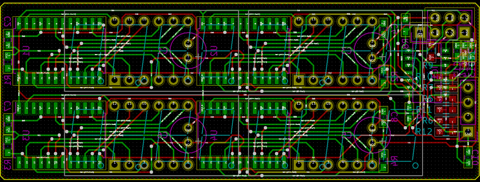
Laying out this board was a nice challenge:

The pin layout of the MAX7221 so does NOT match the pin layout of the LED displays, so there's no way of doing this without a bunch of vias.
There's four displays on the front of the board and a couple of passives for the rotary encoder.
On the back we find the ICs and some more passives. As well as a connector for the rotary encoder and an ICSP header that also doubles as a connector to the main board.
The electrolytic capacitors, displays and connectors are through hole, all the other components are surface mount. The resistors and caps are 0603's. It's tiny, but everything can be soldered by hand. Even by me. And I suck at soldering.
Oh wow, it actually works!
Final shot: the prototype on the breadboard and the completed board next to it.

Sunday, April 24, 2016

Prototyping

I've been working on a little project for a while now. I want to build a programmable DC load, which isn't that complicated in itself. But I also want it to have a nice user interface. I didn't want to go with the standard 4 line character displays that everybody seems to be using. Instead I want to use a couple of segment LED displays to display voltage, current, power and resistance. The main reason for that is that I believe they're easier to read than a cheap LCD. The other reason is that they look much nicer IMHO :)

I have got a nice Hammond sink box in my parts bin that I'd like to use for this project. It's a big aluminium housing that can act as a heat sink. You can just bolt TO-220 packages to it on the inside; pretty neat.

Anyway. This means the dimensions are pretty much fixed and there's not much room to work with. This is what I came up with:

I'll probably move the connectors to the bottom and the rotary encoder to the right, but this should give you an idea of the dimensions.

The user interface will have its own micro controller to handle all the input and "menu" logic. I'll use an ATtiny24A for this (2K ROM, 128 RAM, 128 EEPROM, 14 pins) and four MAX7221's.
I already did some testing with an Arduino Nano to play with the rotary encoder and two displays. That worked pretty well, time to really start prototyping:
Yeah, messy. But nothing spectacular, just scaling up the previous setup. The icky part is using a new micro.
When using a bare ATtiny on a breadboard you only need two extra components: one ceramic cap (100nF) across the power supply pins and one resistor (1K-10K) between VCC and RESET. The ATtiny has an internal oscillator which it will use as a clock by default, so no need for a crystal.

Now for programming these micros. I always like to start of easy, just to make sure the programmer is wired correctly and I didn't mess up the clock settings. So I wrote a small program that toggles a specific pin every second, compiled that and uploaded it using avr-dude and a cheap USBASP dongle. And then all hell broke loose.
For starters, Windows 10 doesn't like the unsigned USBASP drivers, so I had to jump through some hoops to get that done. Then I managed to upload a program, once. After that I got all sorts of verification errors. Thinking the programmer was at fault, (since it was spewing out some warnings), I attempted to upgrade its firmware, bricking it in the process. Yay.
Plan B. Use an Arduino Nano as ISP programmer. That's simply a matter of uploading the AruinoISP sketch and wiring it to the ATtiny.
Still, no success. I could download the existing program from the ATtiny, but uploading a new one resulted in verification errors: it wouldn't write the new program.
Double checking the avr-dude configuration for the ATtiny with the datasheet didn't bring up any errors; that seemed to be okay. Then I attempted to write a custom binary file of all zeroes. That worked! But writing anything else didn't :/
Final step: swapping the ATtiny for a new one. Surprisingly, I was able to upload my program and finally got a blinking LED! But it was blinking too slow, so I probably got the speed wrong. After fixing my code the upload failed again! Comparing the uploaded code to the code read from the micro it finally hit me: bits were only being set to zero! Meaning the memory wasn't cleared before writing! Double checking the flags being passed to avr-dude I noticed the -D flag. Removing that fixed the problem! That only took an entire afternoon :/

So, next problem. The LED was only blinking every 8 seconds, instead of every second. The ATtiny is supposed to run at 8 MHz, but apparently it was only running at 1 MHz. A quick peek in the datasheet revealed the cause: CKDIV8 was enabled in one of the fuses, causing the clock to be divided by 8. All this setting does is set the default value of the clock prescaler to 8 instead of 1. This can either be fixed by burning new fuse values, or by setting the prescaler in code. I opted for the latter, because (a) that's easier to do than googling how to burn fuses, (b) I'm lazy and (c) it will work for new ICs with default fuses.

Two lines of code later, the LED is finally blinking at the right speed :)

Next: porting the existing code...

Tuesday, April 19, 2016

Fun with MAX7221 chips

Just a quick, short post here to show some stuff. I've been playing around with some seven-segment LED's and MAX7221 IC's; great fun. In collaboration with a colleague I've built a build monitor for our Jenkins CI server.

If you're interested in the source code: you can download it here
I'm using Atmel Studio 7 this time instead of the Arduino IDE. I had to roll my own UART interrupt handler in order to get everything to work correctly. The HardwareSerial class of Arduino just didn't cut it. I'm using AVRDude to upload the resulting HEX file to the Arduino.


It's three custom PCB's with a MAX7221 and seven segment display. The PCB's can be daisy chained. You can order the PCB's here. The bottom unit connects to an Arduino Nano. Vcc and Gnd connect to the 5V and Gnd pins. CLK to pin 13 (SCK). DIN to pin 11 (MOSI). CS to pin 9.

This is the schematic for a single PCB:
The PCB layout:
And a 3D render:
Yay, boards!

Doing some debugging:


It's working!


Combined with our CI Traffic light:


Tuesday, October 20, 2015

Synergy on Raspberry Pi


This article was written while Synergy version 1.7.4 was the latest version, I'll try to keep this up to date with new Synergy released, check the end of the article for a change log.

The latest version of Synergy at the last update of this article is: 1.7.6

I love to use Synergy when I'm working on multiple PC's at the same time. It lets you control multiple computers with a single keyboard and mouse. You just move your cursor off one side of your monitor and it appears on the device next to it and keyboard redirects keyboard input as well, neat!
So when I ended up with a second pair of input devices on my desk because of my new Raspberry Pi, having it use Synergy was pretty high on my wish list :)

The standard Synergy client you can get using apt-get is pretty old. It's version 1.3.something whereas the current version is 1.7.4, so that's not going to work. I found this tutorial on how to compile Synergy from source, but that article is outdated as well. Fortunately compiling it isn't that difficult. It's a pretty well documented process, but it doesn't exactly specify which dependencies there are. So here we go!

Step 1: update apt-get

sudo apt-get update
sudo apt-get upgrade
sudo apt-get install gcc cmake libx11-dev libxtst-dev qt4-dev-tools libcurl4-openssl-dev libssl-dev libavahi-compat-libdnssd-dev


The documentation also mentions python and gmake as a dependency but I think those are included in a clean Raspbian installation. I also ran into some problems related to ZeroConf (missing headers), those seem to be included with libavahi.

Step 2: get the source code

Even though you'll need to pay for Synergy nowadays (if you want binaries) you can still get the source code for free: https://github.com/synergy/synergy or you can get a tar.gz from the download page (after a login).
If you have git installed, you can do

git clone https://github.com/synergy/synergy.git

Or get the tar.gz and run

tar -xzf synergy-v1.7.4-stable-c734bab-Source.tar.gz

Enter the folder that was created.

Step 3: build it

Start by configuring the build

sudo ./hm.sh conf -g1

This will generate the needed build script and will check if all prerequisites are present. When that completed successfully you can start the actual build.

sudo ./hm.sh build

This took about an hour to complete on my RPi 2B, so grab some lunch or diner while it's compiling. When it completed successfully, the binaries will be in the ./bin folder.

Step 4: deploy it

This is just a matter of copying the binaries:

sudo cp -a ./bin/. /usr/bin

Step 5: configure it

From this point on you can just follow the adafruit article. The only difference is that I didn't have a ~/.config/lxsession/LXDE folder, it's called LXDE-pi on my RPi instead.

sudo touch ~/.config/lxsession/LXDE-pi/autostart
sudo nano ~/.config/lxsession/LXDE-pi/autostart


And add the following content to the autostart file:

~/.startsynergy.sh

Exit nano (ctrl + x) and make sure you save the changes. This calls the startsynergy script whenever you start LXDE (Lightweight X11 Desktop Environment).
Now create the startsynergy script:

sudo nano ~/.startsynergy.sh

And add the following content:

#!/bin/bash

killall synergyc
sleep 1
synergyc --name pi 192.168.0.16
exit 0


This stops all running Synergy clients. It then starts a new Synergy client. "pi" is the name of the client, you'll need this name when you configure the Synergy server. The IP address needs to match that of your Synergy server.
Finally you'll need to set the rights on the newly created script:

sudo chmod 777 ~/.startsynergy.sh

Step 6: use it!

startx

 RPi on the leftmost monitor, showing the Jenkins dashboard in the browser. The other four are from my main PC (left to right: SourceTree, Eclipse, Jira and Notepad++). And one keyboard/mouse to rule them all! :)

Changelog:
2016-01-05: v 1.7.5 tested, no changes needed.
2016-03-29: v 1.7.6 tested, no changes needed.

Wednesday, September 9, 2015

How do they do it?

Just got some more parts in the mail:
10 nRF24L01+ boards for a whopping $8.12 and free shipping. Seriously, how do they do it and make a profit? I wouldn't be able to send an empty envelope to China for that kind of money...
A couple of years ago I ordered 4 of those boards for $10.40, that's $2.60 each, and now they cost $0.81...

Tuesday, September 1, 2015

First prototyping board assembled!

Got the last pin headers in the mail today!

It's annoying that I still have to rely on wires for this to work properly, but that's the price I pay for not double checking the footprints. The next version (almost done) will have a nice socket header to plug the nRF in.

Monday, August 31, 2015

Colorful pin headers

While waiting for the female pin headers and a few small components to arrive, I partially populated one of the messed up boards to get an impression on how the final board will look. The result is colorful :)

White pins are signal pins, connecting directly to the Nano. Red pins connect to the 5V rail. Yellow to the 3.3V rail. Black pins are ground. Blue pins connect directly to the nRF and turquoise-ish pins are used for whatever is left. Hopefully this will mistakes during wiring. The remaining four rows of connections will receive a 15 pin female header. The inner two rows receive the Nano, while the outer two rows can be used to connect jumper wires. The three large holes were supposed to hold a DC jack connector.

Friday, August 28, 2015

Arduino Nano + nRF24L01+ prototyping board and epic FAIL

I've been working on a prototyping board to connect the Arduino Nano and nRF24L01+ reliably. Bad breadboards and clumsy jumper wires have caused me a fair share of headaches and lost hours already, so I wanted something easy to use and reusable. So I designed a small prototyping board that will do just that, and a bit more.

The board not only connects the two devices, but it also breaks out all of the Arduino's pins, and adds ground and 5V pins next to those as well. So micro servos and three wire analog sensors can be connected directly to the board.

The board also lets you choose to which pin you want to connect the CS and CE pins of the nRF, although the choice is limited to digital pins 4-9. The IRQ pin can be connected to digital pin 2 or 3. And last, but certainly not least, the board has various SPI pin multiplexing options aboard which can be selected. It puts both Nerd Ralph's two wire and three wire solution at your disposal to experiment with :)

Today the first few boards arrived from OSH Park and they look gorgeous.

And the bottom features some nice schematics which explain the multiplexing options:

Nearly all the parts needed to assemble the boards have arrived as well. Of course I couldn't wait and stuck in a Nano to see how it looks.
Pretty neat eh? But. Wait. What? Noooooooooooooooooooooo. I messed up the footprint of the Nano :( I accidentally swapped the rows of pins. Now I need to stick the Nano in the back of the board...
See how the power pins align correctly now?

FAIL

If only I had messed up the nRF footprint as well :( Good thing I only ordered three and not a dozen. Oh well, back to the drawing board. Looks like I'll probably have to layout the entire board again...

I'm really happy with the quality of the boards by the way, the silkscreen is aligned perfectly and the purple board with gold finish looks wonderful. I was a bit worried that the small text would be impossible to read, but it turned out fine.

Thursday, August 27, 2015

AVR Watchdog timer and Arduino Nano issues

In the past couple of day's I've tried to get the watchdog timer on my Arduino Nano to work properly. With success, eventually, but it took some time.

The watchdog timer is a stand alone timer, available in pretty much every 8 bit AVR, that has its own low power, low precision oscillator (clock) and it runs at about 128 KHz, give or take 10%. The watchdog timer can generate a reset signal after a set amount of time, ranging from 16 milliseconds to 8 seconds. You can reset the watchdog timer from your code using a special instruction ("wdr"). The idea behind this is that when your code gets stuck in a loop, or takes too long to execute for various reasons, the micro controller will reset itself, without needing any human interaction.

The watchdog timer in the more recent AVR microcontrollers (including the ones in the Arduini Nano/Uno) have the ability to generate an interrupt instead of resetting the device. Or to generate an interrupt before resetting the device, giving you a chance to store some valuable parameters.This also means you can use the watchdog timer to wake the AVR from idle/standby/power-down mode, perfect for low power applications! Let's look at the datasheet of the ATtiny13A for a second, chapter 7.1, sleep modes:

There are two sleep modes we're interested in here, the idle mode and power-down mode. The first mode has a lot of ways to wake up from, but also keeps the main clock running, meaning more power is used. The latter mode shuts down nearly everything, but can only be woken up from using an external interrupt or the watchdog timer. Now let's have a look at the supply current. Let's assume we're using the 9.8 MHz internal oscillator as clock source and use a 3.3V supply. That's chapter 19.2:

So we're looking at a bit over 2.5 milliAmps at room temperature. Not bad at all, but too much. That's what we'd be looking at if we'd just use a loop and count sheep until we had something to do again. The idle mode is a bit better, chapter 19.3:
About 0.65 milliAmps, that's a major improvement over just burning clockcycles. We'd have to use a timer to wake up though, adding about 0.1 milliAmp (chapter 19.1). Let's look at the power-down mode with watchdog timer enabled, chapter 19.4:
A bit over 4 microAmps, yes, that's MICRO amps. So in power down mode we're drawing less than 1% of the current we'd be drawing in idle mode, that's definitely worth using.

But programming an ATtiny can be a pain. To be more specific: testing and debugging can be a major pain. There's no serial port on those devices, and there are usually no spare pins left anyway. That is why I usually write and test my code with an Arduino before testing it on an ATtiny.

As with any part of the AVR I never used before, I started out simple: set up the watchdog to generate an interrupt every four seconds and toggle the LED pin on the Arduino. That worked, sort of. After four seconds the LED came on, and then turned off, and on, and off, and on, about ten times per second... What's even more annoying is that I couldn't upload any new code while it was doing that. I'd have to pull the USB cable out and plug it back in right before the new code would be uploaded. I double checked and triple checked my code, tried various stuff but couldn't get this simple bit of code to work properly. Finally I started to expect something was wrong with the fuse setting on the AVR, but the Arduino wouldn't let me read or write the fuse bits.

So after a bit of googling I found out I wasn't the only one having this problem. Apparently the fuses on the Nano have been set to always reset on a watchdog timer overflow. And to make matters worse: the bootloader doesn't handle a reset caused by the watchdog timer properly.

The solution (to both problems) is to burn the optiboot bootloader (used by the Uno) to the Nano. For this you'll need a second Arduino, in my case a Mega2560. You'll need to write the sketch "ArduinoIsp" to that Arduino.

Keep it plugged in, it will now act like a programmer. Next you'll need to wire the Nano to your programmer Arduino as described here. Now select the "Arduino as ISP" as programmer.

 As target board, select "Arduino Uno", this will make sure the optiboot boatloader and correct fuse settings will be burned.

 Finally, select "Burn Bootloader". It will burn the optiboot bootloader to the Nano and set the correct fuses!
Now disconnect the programmer Arduino, plug the Nano back in, and set the programmer setting back to "AVRISP mkII". Your board will now look like an Arduino Uno to the IDE, so remember to select that as board whenever you send a sketch to it.

As a side effect, code is now uploaded twice as fast. Yay! Oh, and the watchdog timer now works correctly: the LED now turns on and off every four seconds :)

Wednesday, August 19, 2015

I love OSH Park

This evening I ordered a board I designed at OSH Park. A few hours later I received the following E-mail:
Hi!  We had some free room on one of our Super Swift Service panels,
so we took the opportunity to give you an upgrade.

Your affected orders are:
  * xxxXXXXX - xxxxxxxxxxxxxxxxxxxxxx

The Super Swift Service drops your expected fabrication time from 12
calendar days to just 5 business days.  The same fabs manufacture the
Super Swift panels as our normal panels, so you can expect the same
excellent quality.

Only fabrication time is affected, so the shipping times and method will
remain the same.

Thanks for using OSH Park!
*does a little dance* (using super swift service usually costs $89)

Sunday, August 16, 2015

Sensor module - shrinking


 After finishing the initial design for the wireless sensor modules I realized the placement of the connectors was far from optimal. Having the sensor connector in the middle of the board would mean I wouldn't be able to attach a socket and stick a sensor right in; I'd rather have the sensor connector on a far end of the board.
I also wanted the nRF module to stack onto the board, but as it turned out, I had placed the connector upside down, so the nRF module would stick out instead of hang over the board. So time for revision 2!

I decided to place the ICSP header on the side of the board, just like the USBASP dongles. A few components have moved to the back of the board, including the 3.3V regulator and pull down resistor for the sensor. All in all the board has shrunk about 20% in length, lowering the cost even further, although adding a shrouded connector offsets that saving... Total component cost is now down to less than $2 excluding the sensor and nRF module.

The outline shows how the nRF module is positioned on top of the board, the extra line indicates where the antenna area starts. I tried to keep the overlap of the board and antenna area to a minimum.

Meanwhile I've started programming some bits and pieces, trying out a few new techniques to keep the memory footprint to an absolute minimum. It's going to be a challenge to fit everything in 1 KiB of ROM (just 512 instructions). Interestingly enough, the code is a mix of assembler and C++ templates.

Wednesday, August 12, 2015

Concept: off-the-grid sensor module Part 2

Well over a year ago I wrote a bit about off-the-grid sensor modules. TL;DR: combining an ATmega328 with an nRF24L01+ and using low power mode makes battery powered sensor modules very feasible. Adding a small solar panel and a LiPo battery with charger circuit makes it awesome.

At that time it was just an idea that wasn't that high in my things-to-do-list, but in the past few weeks that idea has become more relevant. In our office I've got a bunch of plants. For those interested, we're trying to grow pepper and paprika plants here, which is a big step up from the indestructible spider plants that are infecting the office building :) I've got over a dozen plants, some of which are not in my room, but I'd still like to keep an eye on them. Now I could just walk into the other room, check on the plants daily and say hi to my colleagues while I'm at it, but where's the fun in that?

Instead of some physical and social labor, I'd rather just have a dashboard to monitor the soil humidity of my plants, because that's what any other sane person would want, right? Besides, I have a Raspberry Pi sitting on my desk that's just begging to be used for something useful.

I initially thought about having a single Arduino Uno connected to a bunch of sensors and to the RPi using SPI, but that's going to get messy with all the wires so I got rid of that idea pretty quickly. Instead I'd rather have tiny sensor modules. There's no need to integrate the nRF24L01+ and the sensor in the design; those can be bought separately for way less money than it would cost to integrate them. Instead the module should just have a socket to plug one of those cheap nRF boards in and a connector for a sensor. And we're going to need power of course. Using an ATmega would be overkill for this kind of project. An ATtiny would be a better choice since it's smaller, uses less current and is cheaper, plus I've got a few in my parts bin.

So what do we need?
  • connector for a nRF24L01+ module board (2x4 pins)
  • 3.3V power supply for the nRF
  • connector for an analog sensor (1x3 pins)
  • programming interface connector (ICSP, 2x3 pins)
Since the module needs to be as small as possible I would like to use an ATtiny in a soic-8 package, those are about 5x5mm in size and have eight pins. Two of those pins are for VCC and GND, and a third one is used for RESET (required if you ever want to (re)program it. So that leaves 5 pins for other uses. Here's a pin layout of the ATtiny I have lying around:
And here's the pin layout for an nRF module:
That's a lot of pins:
  1. GND
  2. VCC (3.3V)
  3. CE (Chip Enable), needs to be controlled
  4. CSN (Chip Select, SPI), needs to be controlled
  5. SCK (SPI Clock), needs to be controlled
  6. MOSI (SPI Master Out, Slave In), needs to be controlled
  7. MISO (SPI Master In, Slave Out), needs to be controlled
  8. IRQ, we're not going to use this.
So we're going to need 5 pins just to control the nRF, occupying all the available pins on the mcu. Fortunately, Nerd Ralph has a brilliant solution to this problem, using just a few off-the-shelf components to multiplex the CSN and SCK pins. This frees up one pin on the mcu which we can now use for other purposes. Ralph also uses an LED to drop the voltage from 5V to roughly 3.3V. That's not something I'm going to use since I also want to be able to power the module from a 6V solar panel or a 3.7V LiPo. Instead I'm going to use a LP2985-N voltage regulator. It has a very low dropout voltage of max 300 mV @ 150 mA, meaning it can deliver 3.3Vout with just 3.6Vin. At 50 mA the dropout voltage is even less than half of that, making it suitable for running off a LiPo battery. Other advantages are that it comes in a very small 5 pin SOT-23 package and costs about $0.25. The ATtiny will also be powered by this regulator since it can't handle the 6V a solar panel can deliver.

Another thing Ralph did was tie CE to VCC. However, this means the nRF can no longer transition between RX and TX mode without powering down.

So, fire up KiCad, throw in all components, wire them together and start laying out the board:

Neat eh? That's just 32 by 11 millimeters, or 1.25 by 0.45 inches. So it's even smaller than the nRF board to be plugged in. The IC1 pads and silk screen look a bit weird, that's because it actually are two footprints on top of each other. The ATtiny13A comes in two SOIC packages: a small one and an even smaller one. This board accommodates for both packages.

The ADC pin can be used as a digital or analog input, or you could use it as a digital output (for controlling a relay for example). The ICSP connector allows for changing the firmware (remember to unplug the sensor and nRF in case your programmer uses 5V).
The bare material cost per board is about $2.70, an nRF module costs around $0.80 and a three pin soil hygrometer costs $1.35. So for less than $5 you've got a wireless module to monitor your plant!

It still needs power though, but I'll leave that topic for a future post.

Wednesday, November 26, 2014

Reflow Toaster Oven - Part 11 - Rewiring

Finally found some time to replace the wiring of the oven. I yanked out the "controls" and redid the wiring. Installed two SSRs on heatsinks and three thermocouples. The result can be seen below.
I used some kapton tape to cover the bare 230V leads on the SSRs. I still need to fix their heatsinks to the bottom of the oven, for now gravity will do the job.
Please excuse the incorrect symbols...
I moved the thermal safety switch from the front to the back because the mains load wire isn't long enough... Mains L connects to the safety switch, so that power to the oven will be cut when the temperature gets too high. From there it goes to the SSRs. Each SSR is connected to one heater element (wires on the left of the photo, front of the oven). The other end of the heater elements are connected to mains null.
I also added three thermocouples in a more permanent setup. Each heater element has one thermocouple, the fiberglass sleeve of the thermocouple has been wrapped in some kapton, and I used a bit of iron wire to strap the kapton covered sleeve to the heater. The thermocouple's junction just presses to the heater. The floating thermocouple in the middle measures air temperature. It's held in place with, again, kapton tape.
I covered parts of the door with aluminium tape, hopefully that will reflect some of the heat.
The difference is noticable; the covered parts of the glass stay cool to the touch whereas the center gets warm. If this works well then I may just have to cover the entire inside of the oven with this stuff, but I'll have to check how well the glue on this tape holds up in the heat first. This is extremely sticky stuff by the way and very thin.

So with the cover back on I have a few wires poking out of the front panel: 3 thermocouple connectors and 2 times 2 wires for the SSRs. Looks like I didn't mess anything up. I didn't blow a fuse when I plugged it in, it didn't catch fire when I turned it on and it didn't kill me when I touched the metal cover. I'm almost disappointed :)